The audio amplifier circuit was developed as a practical project for an electronics engineering course. The objective of the project was to design and construct an audio amplifier capable of delivering quality sound reproduction across a frequency range of 20Hz to 20kHz. The audio amplifier aimed to showcase the application of electronic components and circuitry in enhancing audio signals. By amplifying and shaping the audio signals, the circuit demonstrated an ability to clearly output audio content from various audio sources. The project also aimed to explore advanced techniques for power efficiency and noise reduction to optimize the performance of the audio amplifier circuit.
By carefully designing the circuit for two stage operation, selecting necessary circuit components, performing simulations, and measuring signals on the oscilliscope, the circuit was able to reliably output quality audio signals.
The audio amplifier was developed as an individual project. The goal of the simulations was to provide insight into the output signal characteristics before physically constructing and testing the circuit. This helped to confirm expected signal behaviors before purchasing the circuit components that would be used in the final implementation. The purpose of the circuit measurements was to see how well the predictive simulations compared to the measured results. After completing the project, the value of circuit simulations in circuit design was evident.
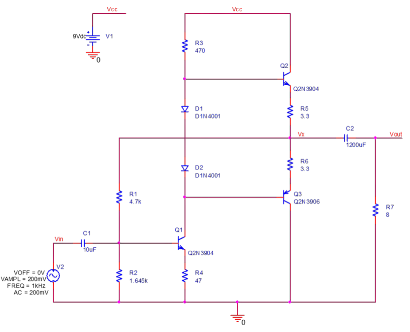
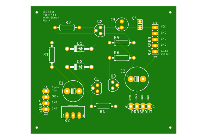
The audio amplifier circuit project involved a comprehensive design and implementation process, encompassing various stages from initial circuit design to final measurements and comparisons. The primary objective was to create a high-performance audio amplifier with a two-stage configuration, comprising a gain stage and an output driver stage. Additionally, the project included the design and manufacture of PCBs to ensure a professional and reliable layout.
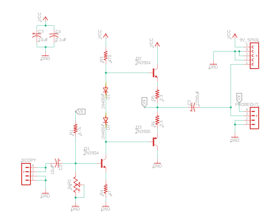
Design Phase: During the design phase, meticulous attention was given to selecting suitable components, including transistors, capacitors, resistors, and other necessary elements. The gain stage was carefully designed using a common emitter configuration to achieve the desired amplification characteristics, while the output driver stage employed a push-pull output configuration to ensure efficient power delivery and minimize distortion. The circuit design was simulated using PSPICE software to evaluate its performance and optimize component values for desired gain, frequency response, and distortion levels.
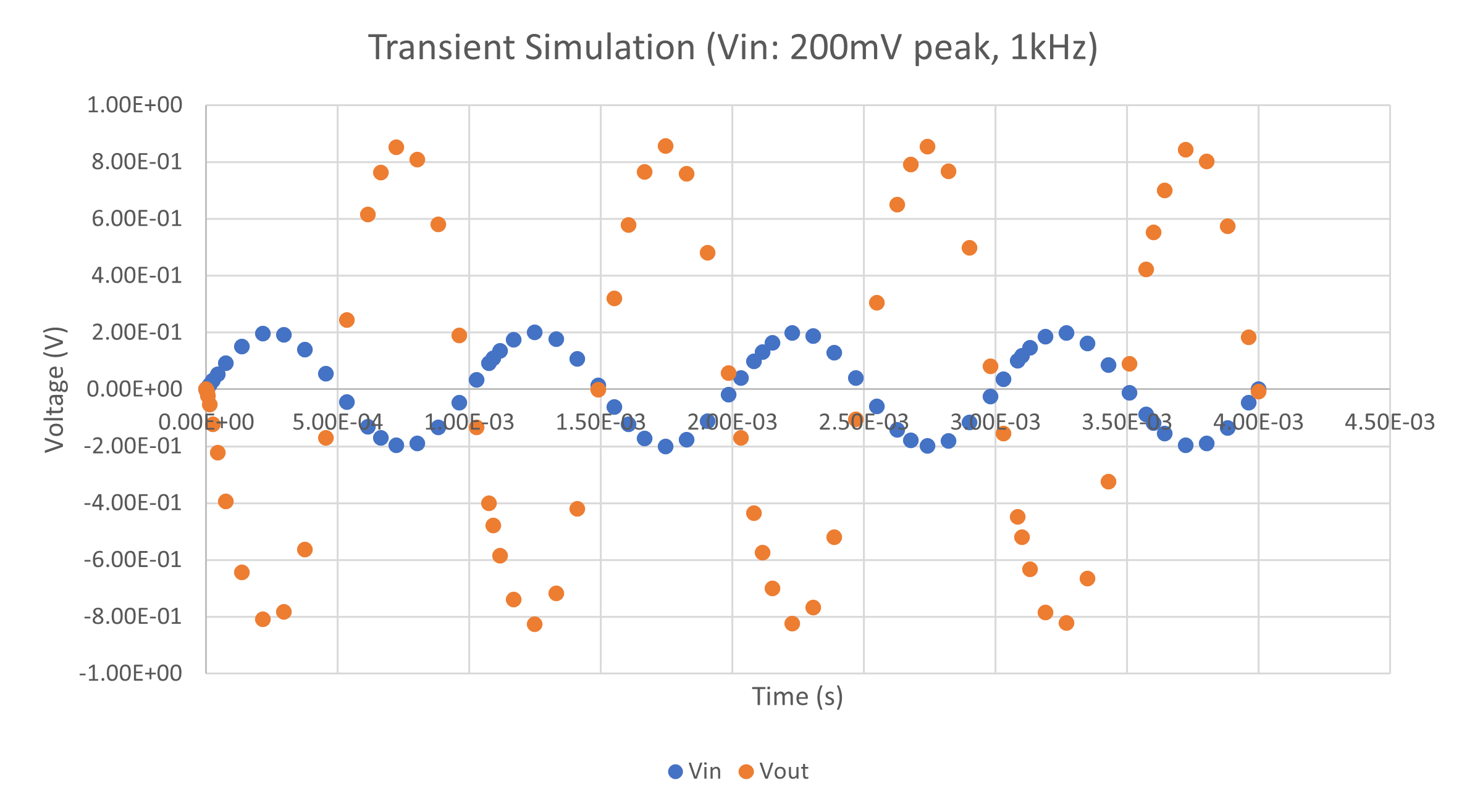
Simulation Phase: To ensure the circuit's functionality and performance prior to implementation, extensive simulation tests were conducted. The designed circuit was simulated using software tools capable of accurately modeling the behavior of electronic components. This phase involved analyzing the circuit's frequency response, gain characteristics, distortion levels, and overall performance parameters. Simulation results served as a valuable reference for verifying the design's feasibility and making any necessary adjustments before moving forward.
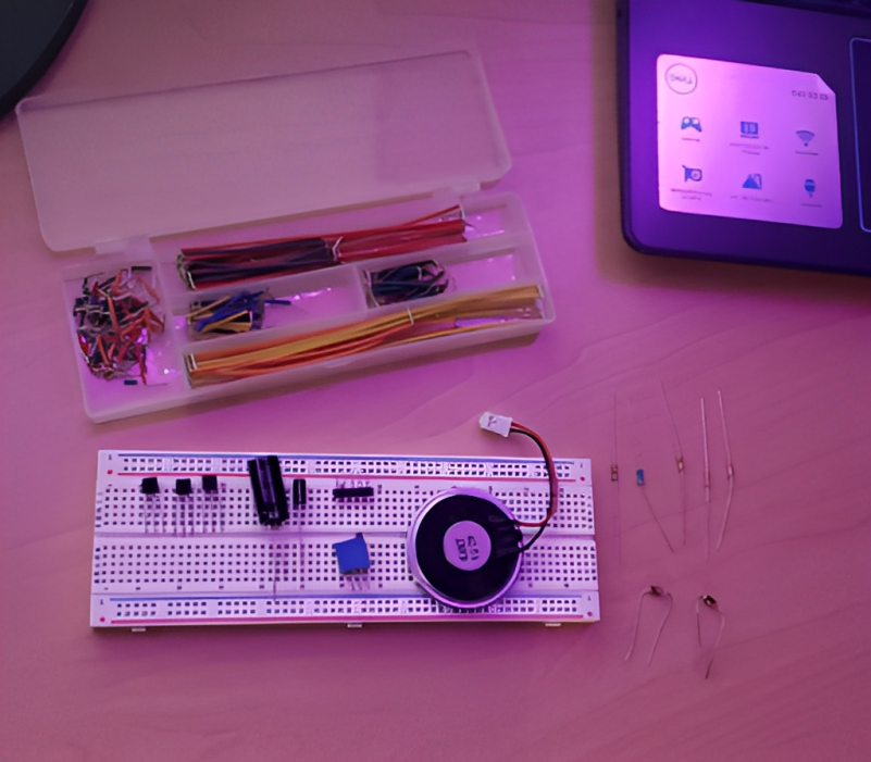
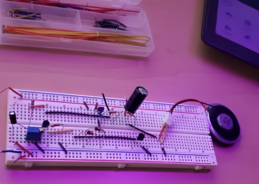
Implementation Phase: With the circuit design and simulation completed, the next step involved the physical implementation of the audio amplifier circuit. This phase encompassed assembling the circuit components on a breadboard as well as manufacturing a custom-designed PCB. Careful attention was given to the layout and interconnection of components to minimize noise and unwanted interference. Soldering techniques and best practices were employed to ensure reliable connections and proper heat dissipation.
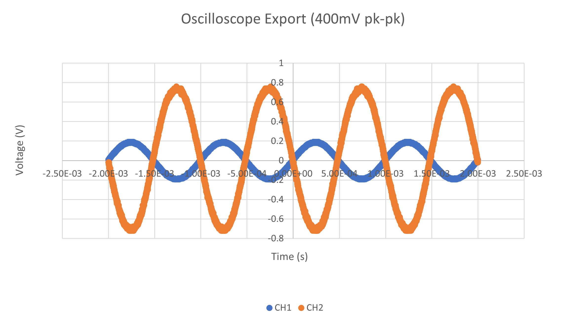
Measurement Phase: Following the circuit's physical implementation, thorough measurements were performed to evaluate its performance. Various parameters, such as frequency response, gain, total harmonic distortion, and output power, were measured using specialized test equipment, such as oscilloscopes and function generators. The measured results provided valuable insights into the circuit's performance and allowed for comparisons with the simulated data.
Comparison and Optimization Phase: In the final phase of the project, the measured results were compared with the simulation data to assess the circuit's performance against the design goals. Discrepancies between simulated and measured results were analyzed to identify potential sources of error and areas for improvement. The recorded results from the oscilliscope compared well with the original simulation results, however, the ground connections were changed to star configuration to reduce noise and improve signal integrity.
Conclusion: The audio amplifier circuit project involved the complete development cycle, starting from circuit design and simulation, through implementation and PCB manufacturing, to measurement and comparison with simulated results. This comprehensive approach allowed for a thorough understanding of the circuit's behavior, performance evaluation, and refinement to achieve optimal audio amplification. The project not only enhanced technical skills in circuit design and analysis, but also provided valuable insights into the practical aspects of audio amplifier development, paving the way for future projects in the field of audio engineering.